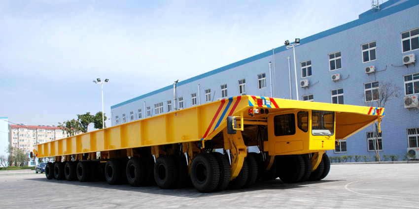
Shipyard transporter is a vehicle which can transport ship parts in shipyards. It isn’t the same as the modular trailer or SPMT that can carry up to 1000tons by only 1 set.
The Shipyard transporter has a larger working platform and higher Loading surface as shown.
shipyard transporter
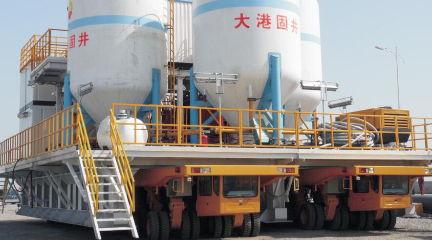
The shipyard transporter became a lot useful in the transportation of heavy industrial equipment, vehicles and ships. Industrial facilities such as power plants, shipyards and factories often need very big delicate objects that re normally heavy.
The movement of such objects within the buildings or to the test locations becomes almost impossible through the use of conventional lifting equipment such as forklifts.
The invention of the shipyard transporter came about because of the following scenarios:
- The most commonly used method of lifting and transporting objects within industrial facilities was mainly through the use of cranes. The gantry crane was and to this day been used for lifting heavy objects through the use of a hoist attached to a trolley running in a horizontal format along the gantry rails. The gantry crane however could not suffice when lifting much heavier objects such as ships on a shipyard. The equipment is disadvantaged when required to lift big size, particularly high objects. Another challenge with the gantry crane is the maneuverability efforts. Lifting equipment in this category usually found in many industrial facilities is the overhead crane system. This works with beams usually mounted on the side walls of a building. For the overhead crane unit, the hoist mounted on a trolley carries the load as it moves along the beams. The main disadvantage with this arrangement is the inability to move the object from one yard to another especially outside the building past where the track system of the overhead crane extends.
- The shipyard transporter is great solution to the incapacities also realized with the use of very heavy capacity forklifts and trailers. These two need an extended space to operate from and a place for heavy point-loading on the ground surface during operations. These heavy capacity forklifts are usually on solid tyres or limited mechanically balancing suspension depending on the tyres’ compression for compliance to rugged operating surfaces. Very heavy capacity solid tyre trailers are restricted to mechanical equalizing suspension. That means that the provision maneuverability and compliance on congested floors and irregular floors is limited. These have sharply diminishing abilities for loads over 40 tons in weight.
Read More:
SPMT Ultimate Guide – Self-propelled modular transporter Design & Specs
What is a Modular Trailer? – Learn Hydraulic Modular Trailers Specs & Designs
Shipyard Transporter Ultimate Guide – Learn the Technical Specs
Get Detailed Specifications Now!!
Table of Contents
1. Concept Development of the Shipyard Transporter
The need for transporting much heavier loads inside an industrial facility where objects are over hundreds tons in weight led to the development of the Shipyard transport, In Plant-Self-Propelled Modular Transporters (IP-SPMT).
These are low-profile deck self-propelled transporters with multiple axles and independent suspension axle assemblies basically used for carrying and transporting heavier loads up to hundreds of tons.
The IP-SPMT is basically powered through internal combustion engine-electric means and consists of 6-12 or even more on-center rotation assemblies of axles.
These axles can be steered independently through varying motor direction and speeds.
However, IP-SPMT devices and these other movers cannot suffice in certain applications owing to the fact that IP-SPMT needs more axles to carry cargoes of large dimension.
The shipyard transporter has larger working platform and higher loading surface from the ground.
Here are the common specs for reference:
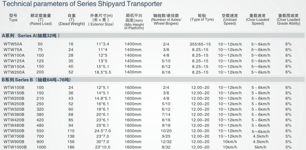
Get Detailed Specifications Now!!
2. Design and Construction
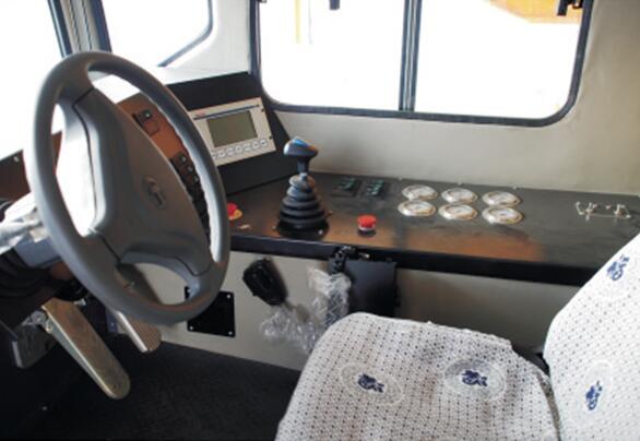
The SHT is a special-purpose vehicle which has the function of hydraulic self-lifting and self-propelled. It is suitable for transporting heavy loads of shipyard.
The SHT consists of platform frame, wheel bogie with drive, wheel bogie with brake, power pack, hydraulic lifting system,
hydraulic driving system, hydraulic steering system, brake system, cab, vehicle electrical system and micro-electric control system.
3. Frame structure and platform cover
The shipyard transporter is a multi-wheeled transport vehicle with capabilities of loading and carrying very heavy objects as it cross over uneven surface without torquing the load.
The frame has high rigidity to against bending, and has good flexibility when it bears torque.
The whole vehicle is strong and rigid enough to bear uniform load. On the obvious place of steel structural frame, there are load distribution signs and warning signs.
There are lifting eyes on the steel structure body of the vehicle which are used for hoisting.
There are steel cover plate on the lift platform which could be disassembled. The thickness of the steel cover is not less than 5mm.
Get Detailed Specifications Now!!
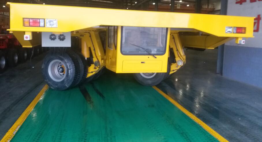
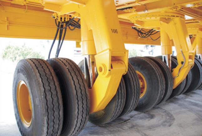
4. Wheel bogies
The wheel bogie consists of rocker arm, bogie frame, slewing ring, pendulum axle with brake or pendulum axle with drive and suspension cylinder etc.
The suspension system is mounted on the slewing ring. When the road is uneven of transverse direction, the axle will swing to compensate.
If the road is uneven of vertical direction,the group of hydraulic lifting cylinder can provide longitudinal compensation .On the slope, the platform could keep balance by adjusting the suspension cylinder.
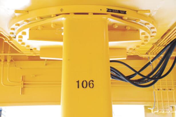
The slewing ring adopts single-row rotary supporting way. The inner ring and outer ring of slewing ring adopt high quality alloy which is made by forging .It can bear heavy load.
Get Detailed Specifications Now!!
5. Hydraulic Systems and Control
- Hydrostatic drive system
Shipyard transporter is equipped with static hydraulic driving system which can ensure the vehicle run and accelerate smoothly.
It can make the required power of vehicle matching with the output power of engine in any different conditions .It also can prevent the engine turn-off which cause by the engine and driving parts overload.
The speed of diesel engine and the SHT is controlled by the pedal accelerator.
- Hydraulic Steering System
The hydraulic steering system on the other hand is an open-loop system. The open loop system has a variable pump used to integrate the load-sensing together with the pressure-cutting-off flow control capabilities.
The output flow of the variable pump is also adjusted based on the need of the load to save energy.
Through the use of the pressure-cutting-off flow control function, the utmost output pressure of the pump can be restricted in order to protect the system.
Hydraulic Lifting System
- Hydraulic Lifting System
The hydraulic lifting system together with the hydraulic steering unit has a common open-loop variable pump.
Hydraulic oil coming from the pump is supplied evenly to the lifting cylinder. This makes it possible to lift the platform at a leveled position.
- Hydraulic Cooling System
There are two system gear motors that are used to drive the fans to cool down the composite radiator. One of the pumps is used to supply the hydraulic oil under pressure to the system gear motors.
- Hydraulic Break System
The shipyard transporter achieves the brake function and the parking brake through hydraulic means where the brake cylinder pushes and releases the brake drum.
Inside the cylinder, there are springs that are used to keep the vehicle in the parking brake status in the absence of pressure oil inside the cylinder.
A manual pump is also part of the braking system and its main function is to release the brake should there be no power of the vehicle.
- Hydraulic Suspension
The hydraulic suspensions are categorized into wheel bogies with brake, wheel bogies without brake and wheel bogies with drive. Ideally, the hydraulic suspension consists of a bogie frame,
hydraulic suspension cylinder, rocker arm, axle with brake, or without brake or with drive, tyre and so on.
The gear shaft sleeve is welded on the frame of the bogie and the hydraulic suspension cylinder located between the rocker arm and the bogie frame.
The rocker arm is used for linking up and bearing the road. This setup creates the hydraulic suspension adjusting range of + or -350mm.
The motor and the reducer are attached to the wheel bogies that have drive and are use to give the driving force needed for the vehicle.
The wheel bogies that have been installed with brakes have axles with brake and have a brake cylinder on it that actualizes the parking brake and service brake for the vehicle.
The three different types of wheel bogies are all provided with mechanical stoppers to control and limit the maximum position and
make use of the minimum suspension cylinder stroke to control the lowest position normally used for vehicle transportation, replacement of tyres and also needed when repairing wheel axles.
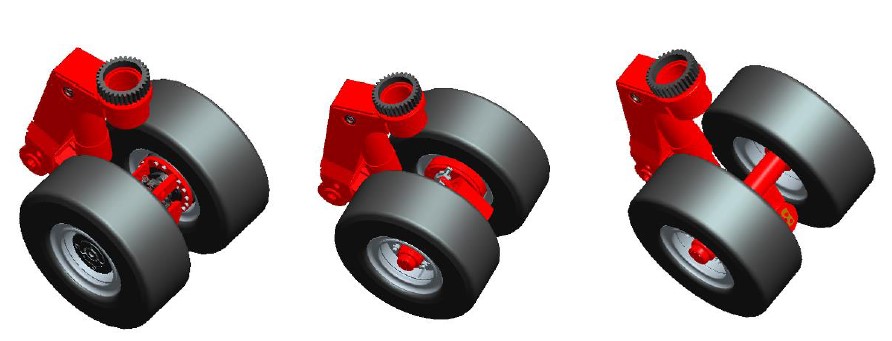
wheel bogies with drive/wheel bogies with brake/wheel bogies without brake
The process of making a replacement of the tyres unloaded or on full load are as follows:
- Lift down the bogie with the tyres that need a replacement
- Shut off the suspension cylinder’s ball valve
- Lift up the entire shipyard transporter
- Make the tyre replacement
Once the tyre replacement is done,
- Lift down the entire shipyard transporter up to the lowest point
- Take off the locking pin
- Open up the ball valve on the suspension cylinder
- Lift up the entire shipyard transport to the recommended driving height
The recommended replacement tyre us the solid quality type 355/65-15/9.75, the most suitable option that can meet the loading bearing requirements of the entire vehicle of up to 1.1times dynamic loading.
The rims are of different types: one with the wheel bogie having a drive and the rim on the wheel bogie that has brake and that without brake.
By way of making adjustments to the hydraulic suspension system, the support system of the shipyard transporter can create 3 or 4 points of support to brig balance through the equal distribution of loads on all the tyres.
Additionally, this makes the transportation on the rugged road reliable and safe.
Each of the suspension cylinders is installed with 2-direction anti-break valve to cover up should the pipeline be broken.
The increasing flow will suddenly cause a differential pressure between the inlet port of the valve and the outlet port to block the broken pipeline. This measure is crucial in preventing the cargo from inclining to one side.
Get Detailed Specifications Now!!
6. Electronic Multi-Mode Steering System
The electronic compound multi-mode steering system is typically made of steering hydraulic pump, oscillating cylinder, proportional sandwich valve, angular sensor, rack-and-pinion steering device and the electronic calculating element.
The rack-and-pinion unit comprises oscillating cylinder cases, angular sensor, oscillating cylinder, rack and pinion among other elements.
The oscillating cylinder cases have the function cross girder and are welded with the frame with great manufacturability and enhance the reliability of the structure.
The angular sensors are well attached on each of the wheel bogie.
The moment the remote controller sends the steering signal, the electronic calculating element will respond by calculating the theoretical inclination or angle based on the steering mode.
This will the make a comparison with the feedback as provided by the angular sensor where the wheel bogie will calculate the amount of electric current of proportional sandwich valves to facilitate the control of opening.
Ultimately, the wheel bogies will be pushed through the hydraulic steering cylinder to get to the desired destination positions through the steering.
The Shipyard transporter can attain 8 steering modes: each wheel steering along, each wheel steering cross, front wheels stressing, rear wheel steering, diagonal steering along, diagonal steering cross, circle steering and rest mode.
It can also set other modes of steering based on the operation needs. The steering modes of the multi-coupling transporters are usually similar with those of a single transporter.
When the difference of the steering angle of the wheel bogie is more than 8°, the system driving the vehicle will shut itself off automatically. This is a safety configuration that stops the vehicle and sound an alarm.
Conclusion
The shipyard transporter is a transport mainly used in the transportation and movement of ships between shipyards or to their docking stations.
Most of these liftings and movements except by SPMT have mainly been done in-house. Therefore, the shipyard transporter is a designed in a way that can offer much more capabilities for weighty objects.
Additionally, the nature of the design does not interfere with the transporter’s travelling ground which has been a challenge with previous transporter designs.
Most of the in-built systems for the shipyard transporter are hydraulically controlled.
This is a detailed document with information about a shipyard transporter, its design considerations and structure and how it can optimally be used to produce the desire results in operations as would deem necessary for its use.
Finally i am up-to date with Shipyard transporter modular trailer. Thanks a lot Anterttrailer will surely visit again!